Project - Obsidian
Introduction
Project Obsidian was born from the idea of creating a personal sound system able to reproduce powerful base and precise staging. I used components and tools I had in hand in order to pass from idea to reality.
This is a work in progress, and I acknowledge it's not perfect and could benefit from significant optimization. Nevertheless, I want to share with you my approach on loudspeaker design and overall workflow process.
In practice, this is a 2.0 sound system composed of 4 passive channels. Each channel is designed to provide complete control over each individual loudspeaker.
Hardware Components
Low and Mid-Low Frequencies
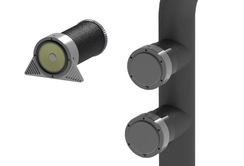
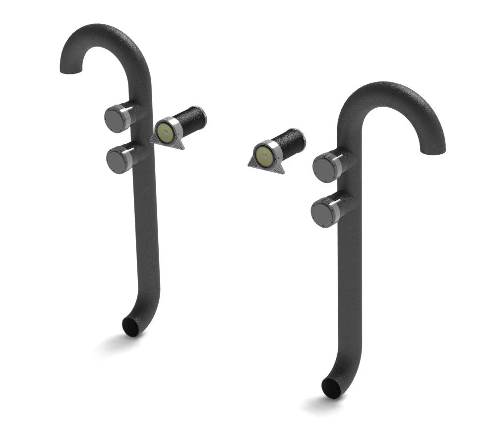
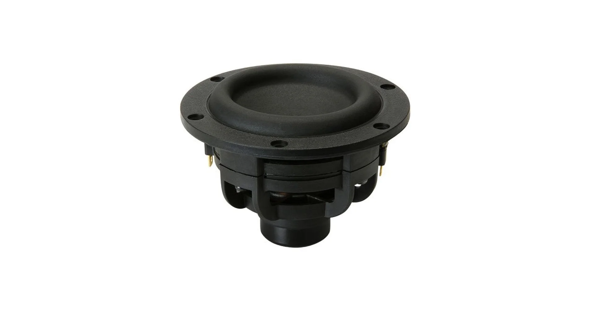
For the low and mid-low frequencies, I chose to use 80 cm diameter pipes to create transmission lines paired with the Tang Band W3-1876S Mini Subwoofer. These loudspeakers were selected for their good excursion capabilities and favorable BL parameter, which is the foundation for a punchy and impactful sound.
Mid and High Frequencies
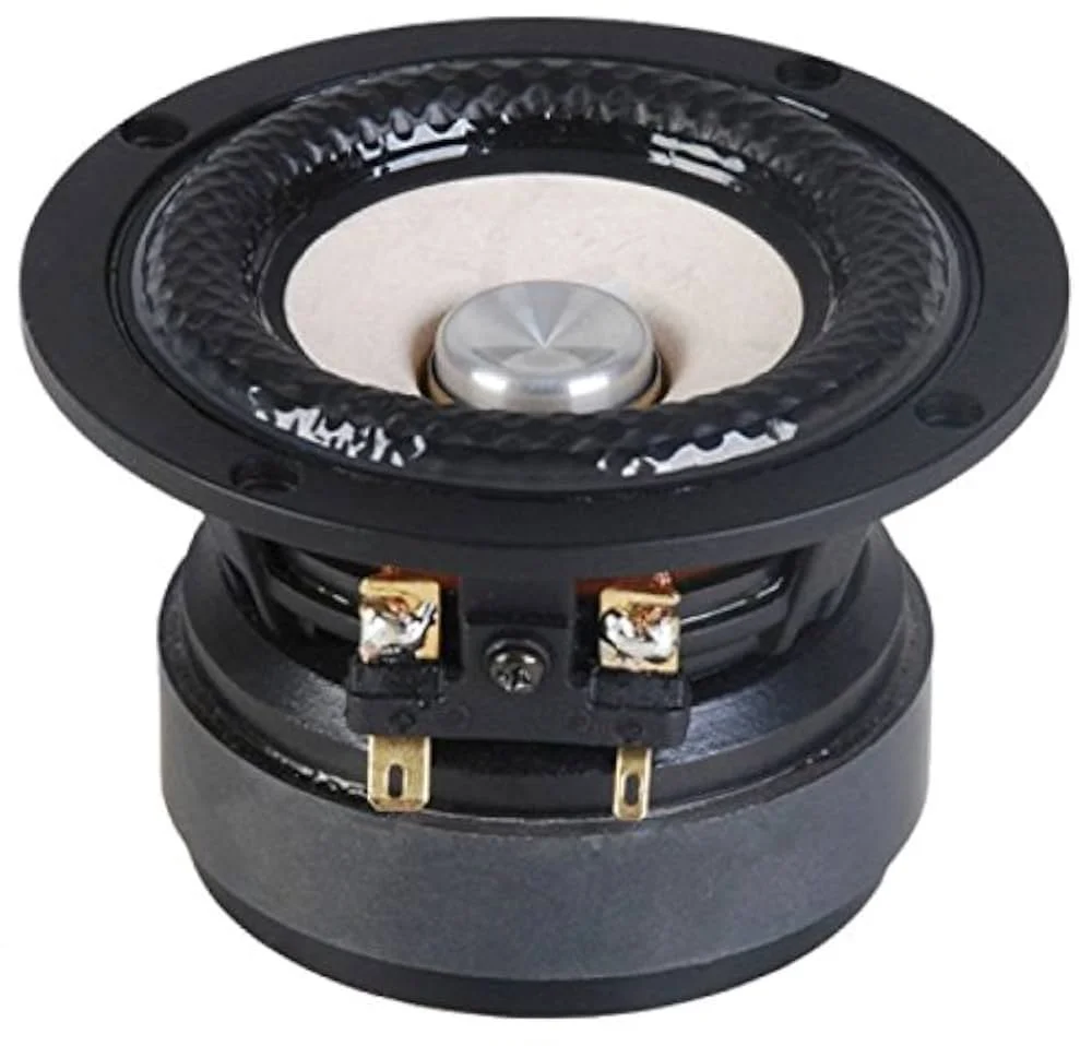
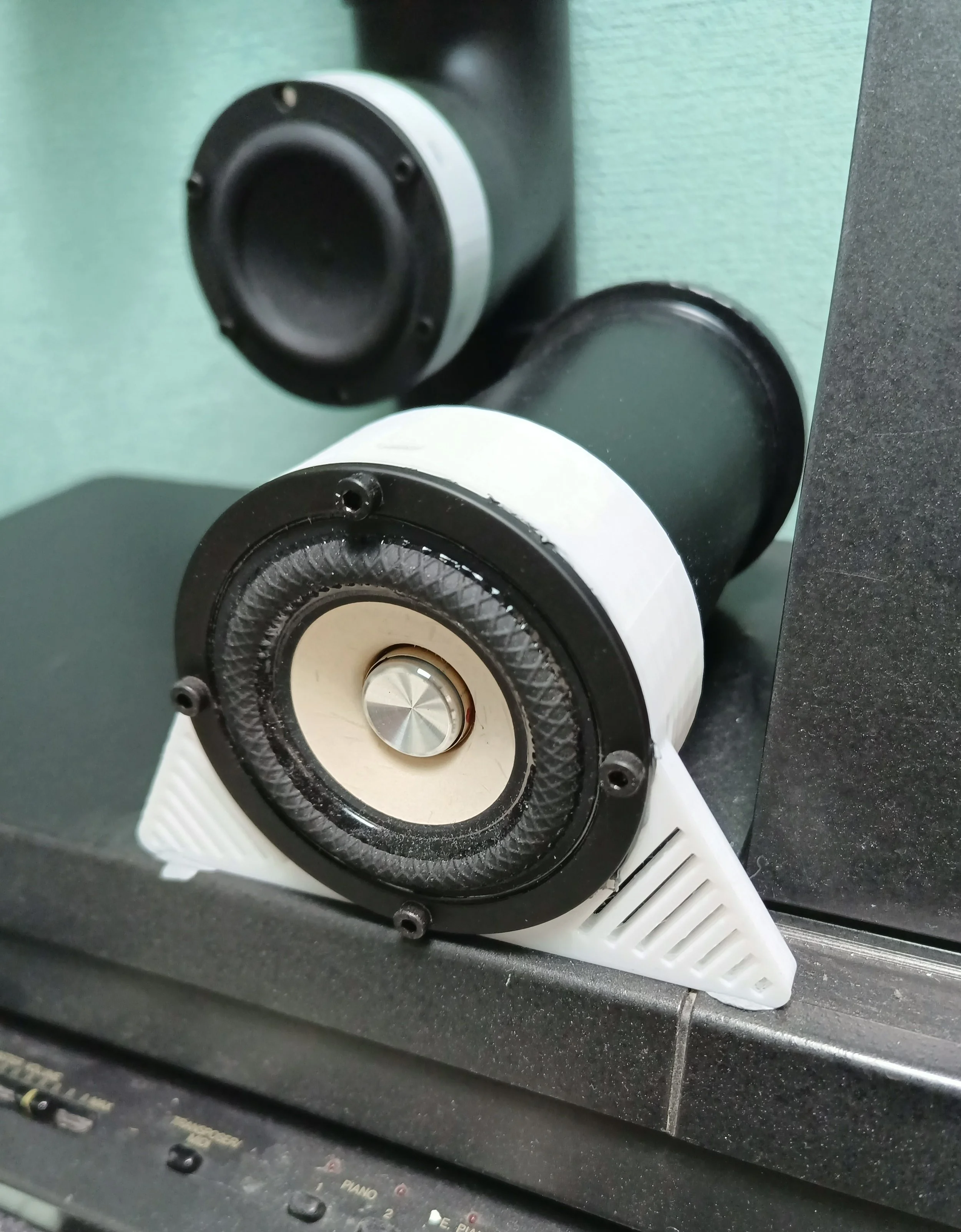
For the mid and high frequencies, I decided to use the Tang Band W3-2141 3" Paper Cone Full Range Driver (8 Ohm). These drivers not only have an appealing aesthetic but also showed promising performance.
DSP and Amplification
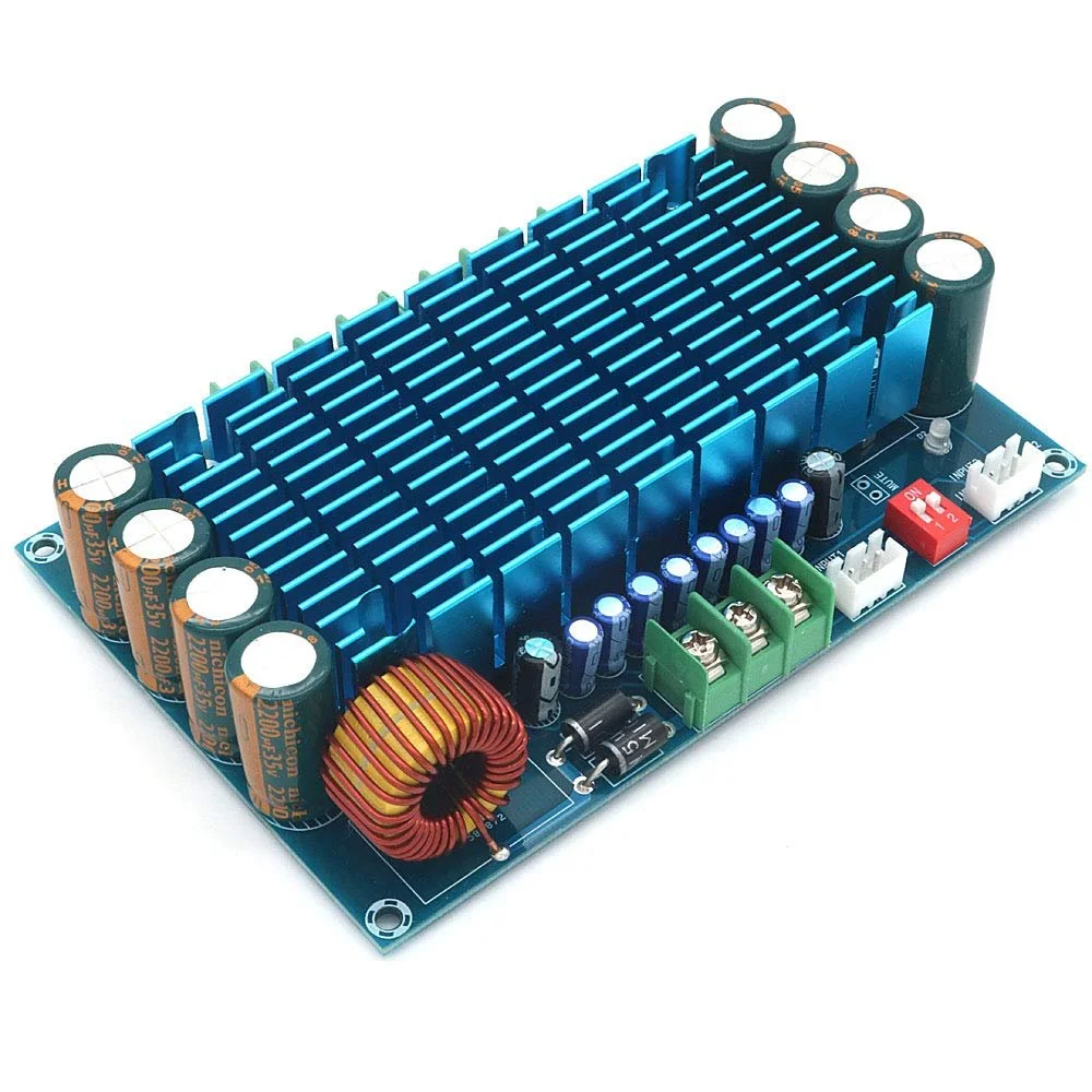
For the DSP, I utilized what was available: an ADAU 1701 compact module paired with a 4 channel TDA7850 embedded in the XH-M180 board. This will provide 50W of power per channel.

Low Frequency Performance
Regarding the low frequency tower speakers that provide the bass foundation, here is a quick simulation showing how I calculated the transmission line characteristics and the overall response.
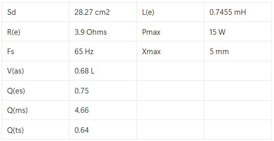
I would have liked to measure all the Thiele and Small parameters individually using a Klippel system with the Linear Parameter Measurement (LPM) module and Large Signal Identification (LSI) for characterizing my loudspeakers. However, you could use the DATS V3 as an alternative to determine the real driver characteristics compared to the datasheet. Just a little reminder that it's a good idea to let the loudspeakers "burn in" or be used a little bit to loosen the mechanical suspension. In this case, the obtained measured parameters for the Tang Band W3-1876S Mini Subwoofer are the following:
The idea is to construct a quarter resonance transmission line (λ/4) that is open at one end and closed at the other. This is due to the fact that a quarter-wave line will have a strong standing wave at the output that boosts low frequencies due to the fact that at this point, a pressure node and a particle velocity antinode are formed. This is the point where air particles are moving the most. This behavior is basically the nature of a resonator. Now, how can we calculate the length and width of the line? We need the following driver information:

Once we have this we neeed to match the drivers resonance frequency Fs with the following formula

Regarding the diameter, it is recommended that the pipe's surface area matches the driver's surface area for proper acoustic coupling. A surface area that is too large will spread out the airflow and cause losses, while a surface area that is too small will choke the airflow. In this case, since a double driver configuration is used to compensate for driver sensitivity, the required surface area equals 56 cm². The closest commercially available pipe diameter is 80 mm, which provides a surface area of 50.26 cm². This will cause some airflow restriction, but it is manageable.
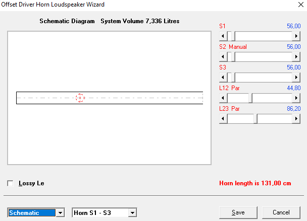
For transmission line designs, the software HornResp is utilized. To determine the optimal loudspeaker driver placement, a simulation was conducted by varying the driver's distance from one end of the line to the other. Ultimately, the goal is to achieve smooth acoustical power combination.
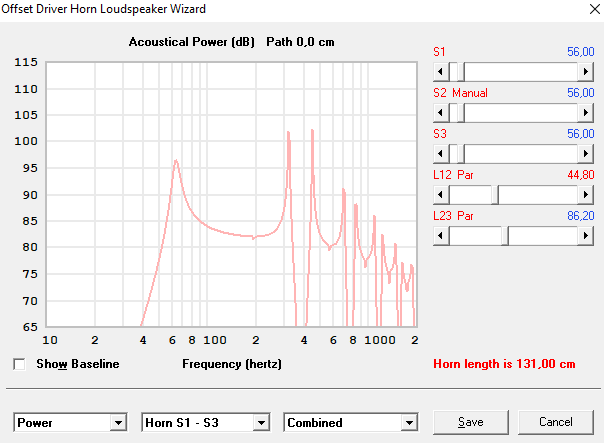

However, one can see that certain resonances are present in the system. In order to attenuate them, one can experiment with adding different amounts of absorbent material inside the transmission line. Different possibilities can be considered, but don't forget to take into account the feasibility of construction.
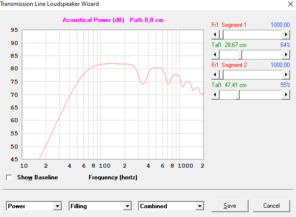

The idea is to optimize acoustic power while decreasing resonance behavior with the least amount of material installed in feasible positions.

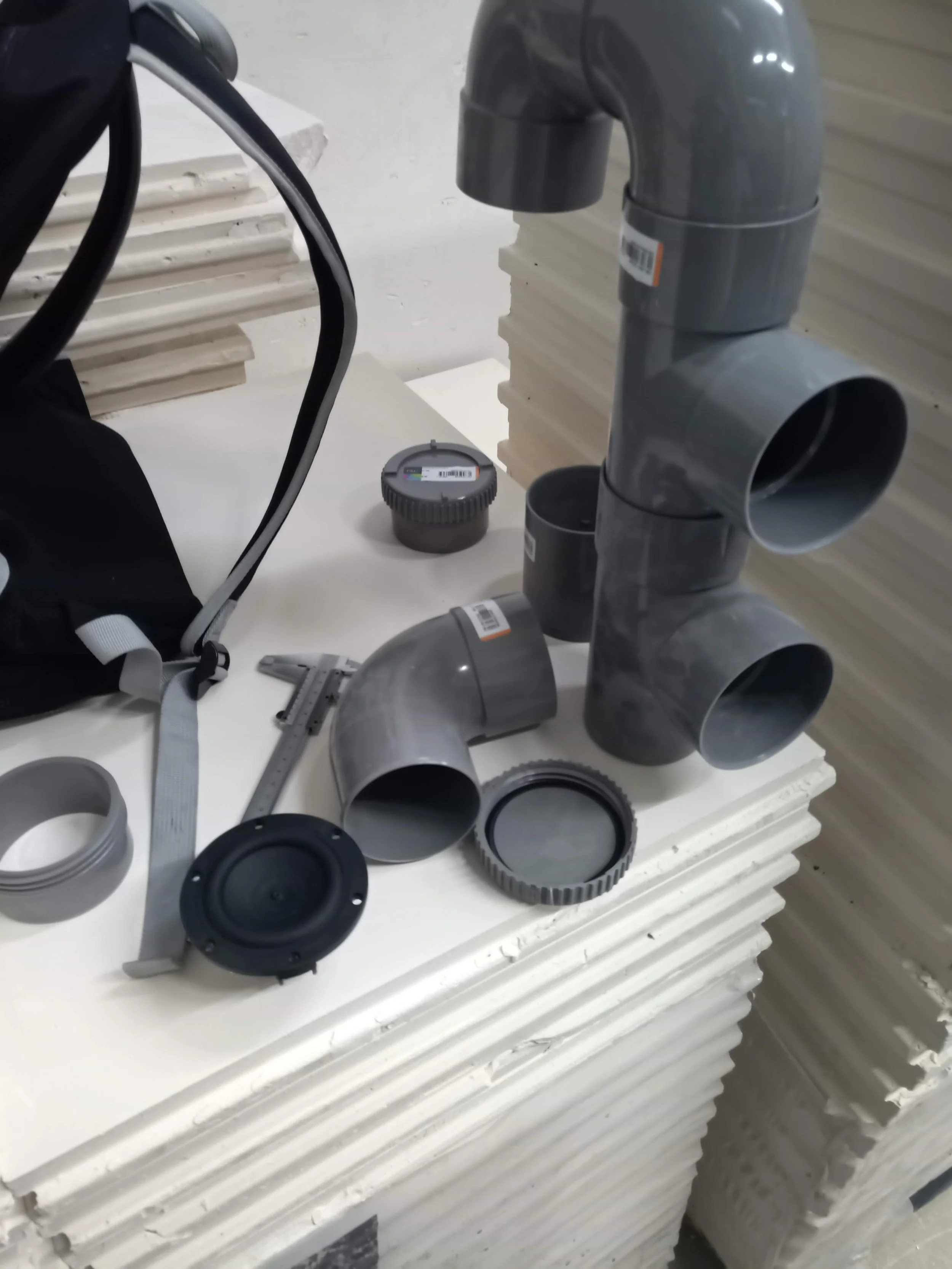
Once the simulations are completed, time to go to the hardware shop and search for the components.
Add a little bit of extra flavor and…
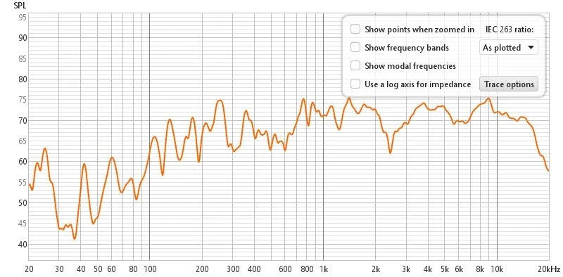
Here the initial measurements without any signal processing:

Measurements were taken using a calibrated microphone positioned 1 meter from the loudspeaker along its axis and using REW software. However, these measurements were not conducted in an anechoic chamber, meaning that room reflections may have affected the data.
The results show that while certain resonances are present, a generally linear energy pattern can be observed from 60 Hz to 300 Hz.
Mid and High Frequency Performance
For the mid and high frequency section, here is the overall response of the loudspeaker.
It can be seen that certain corrections need to be done but energy between 300Hz and 16kHz can be obtained.
Now time to tune the system.
System Configuration
In order to really improve the system, a tuning session is going to be dedicated. The objective is fixed in improving 3 main subjects.
Refine overall Frequency response balance accordying to a personal target curve.
Centered staging and imaging effect.
Reduced distortion and resonances at high volumes.
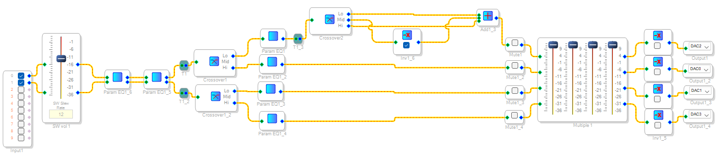
The following audiopath will be followed in order to accomplish the last mentioned goals.

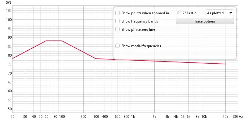
Dedicated taget curve utilized as reference.
Now a brief comparison between before and after tuning of the 4 channels and measured at a central listening position is presented.
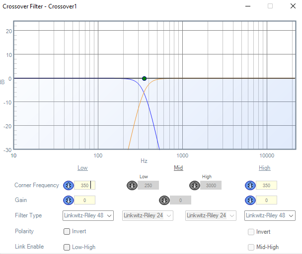
However, first it is important to mention that a 2nd order Linkwitz riley was used in order to avoid affecting magnitude and time alignment.

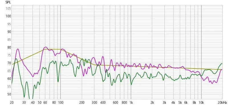
Here under the measurements of the Left channels woofers in yellow and mid range in violet and their corresponding curves after equalization. Woofers in green and mid range in red


Subsequently the measurements of the Right channels woofers in violet and mid ranges in purple among their corresponding individual channel equalization.

Once each individual equalization is done, the 4 channel configuration is measured and this is the result.
Not bad… but can be improved for shure. It can be seen that in the region between 187Hz and 260 Hz there is a negative dip caused certainly by acoustic deconstructive interference. A trick that can be used to solve this, is to make an out of phase measurement and compared it with an in phase measurement.

In Violet our original graph and in green the measurement with the left channel out of phase. As you can see the negative dip energy that its lost, can be recover just by flipping the phase in between one of the woofer channels. Resulting in the following graph.
In blue, the dedicated measurement which results from flipping the phase between 187Hz and 260 Hz. However, it can be seen that beneat this ranges, neighboring frequencies are affected thus a general eq is applied to compensate for this losts and get back to our reference target curve.

Finally, in order to protect the system from over excursion and to diminish distortion at high volumes, some extra protection filters are applied. This come in the form of two 2nd order General High pass filter applied at 50 Hz and a peak to reduce the resonance at 26 Hz.


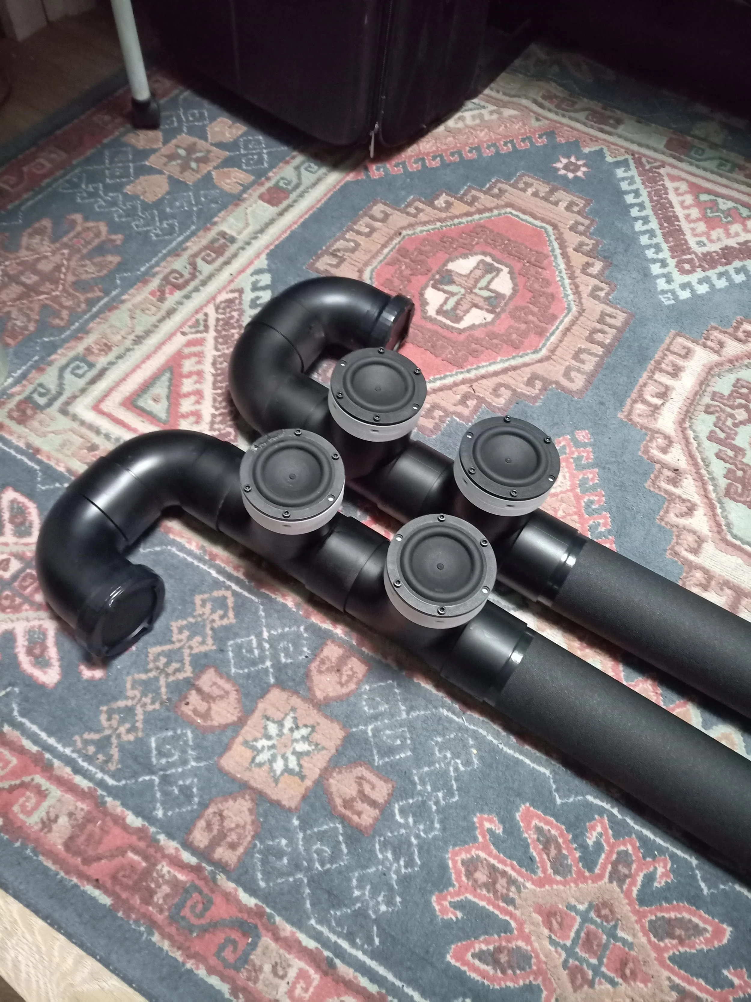
Final Construction view on site :)
Conclusions and Future Improvements
At the end a frontal 4.0 system achieved the 3 main objectives proposed. The construction of the transmission line coupled with high excursion woofers provides deep and powerful kicks while mid ranges provide a central and precise staging. Dsp tuning improved significally the system response. Measurements are shown to show the results step by step.
Several enhancements are planned to further optimize the system:
Replace analog connections: Use I2C instead of auxiliary inputs and outputs to reduce hiss.
Expand channel configuration: Add a central loudspeaker to enhance staging effects and incorporate a dedicated subwoofer for deeper, more impactful bass response
Refine system timing: Improve time alignment and gain compensation across all channels via time allignment tools.
Thank you for reading this post and hope you can apply some of the tools or ideas for your next loudspeaker construction.
Shout out to the following creators that share a similar pasion and appreciate good sound!
Do not hesitate to contact me if you have any comments, questions or would like to discuss or colaborate.
Keep building, keep dreaming!
Santi.